| | August 2019 • Important note
Some information on this page is now outdated.
For ambisonic production, we recommend using the following DAW and VST plug-ins:Aalto University SPARTA and COMPASS plug-ins | IEM Plug-in Suite | Matthias Kronlachner's ambiX plug-ins | Blue Ripple Sound's O3A Core suite
We recommend the following book as the reference on Ambisonics audio production, including native B-format recording:
Ambisonics: A Practical 3D Audio Theory for Recording, Studio Production, Sound Reinforcement, and Virtual Reality
 The original Nimbus-Halliday setup, with one B&K omnidirectional and two Schoeps figure-8, with its specially designed microphone holder. The original Nimbus-Halliday setup, with one B&K omnidirectional and two Schoeps figure-8, with its specially designed microphone holder.
Image: Paul Hodges
| | Historical Background Soundfield-type microphones have four cardioid or sub-cardioid capsules arranged in a regular tetrahedron. The stream of four audio signals produced by this arrangement is called A-Format. In Ambisonic, the A-Format is never used on its own, unprocessed. It must be converted to the B-Format. This B-Format, out of a Soundfield-type microphone, is made of one virtual omnidirectional mic coincident with three virtual coincident bidirectional (figure-8) microphones, orthogonally arranged relative to each other.
For people who don’t have access to a Soundfield-type microphone, or simply don’t want to use one, it's possible to arrange together standalone microphones that have the needed directional characteristics, thus allowing to record sound directly in B-Format. In fact, such an arrangement of one omnidirectional and two bidirectionals has been used for many years by the production team at Nimbus Records: the arrangement was called Nimbus-Halliday, for Dr. Jonathan Halliday who developed the idea. In recent years, this approach has been dubbed Native B-Format.
This picture is of the original Nimbus-Halliday setup, comprised of one B&K omnidirectional mic and two Schoeps bidirectional (figure-8) mics, with its specially designed microphone holder. Image: Paul Hodges | | | 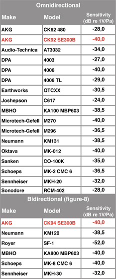
| | Microphone Choice There are several omnidirectional microphones that can be used for the W channel. Small diaphragm condensers are preferable since the small size will contribute to better coincidence. Also look for the best omnidirectional pattern: higher frequencies and the 180° axis is where some omni mics fare better than others. The choice is more limited when it comes to the X and Y channels. Small and single diaphragms are almost mandatory. Again, they need to be small to allow better coincidence in the assembly and single for symmetrical front-back directivity and frequency response. While large double diaphragm microphones that can be set to fig-8 are often more readily available than dedicated fig-8, B-Format does need symmetrical behavior in the X and Y channels. So small diaphragm condensers and ribbon microphones are the best candidates. For uniform directional covering and frequency response in recording, X and Y microphones have to be of the same make and model. Matching frequency responses between the omni and the fig-8s is necessary since it will provide a more coherent decoding. Matching sensitivities is not an absolute necessity, but the figures need to be known. If the sensitivity of a microphone is only specified in mV/Pa, you can convert it to dB (re 1 V/Pa) with this tool. It is worth mentioning that the Josephson C700S microphone outputs horizontal-only native B-Format, but in that price range, one can also choose to go for a SoundField model. | | |  Native B-Format assembly with Schoeps mics. Native B-Format assembly with Schoeps mics.
Image: Angelo Farina
 Native B-Format assembly with AKG Blue Line mics. Native B-Format assembly with AKG Blue Line mics.
| | Microphone Setup If we consider the Nimbus-Halliday as the ideal native B-Format microphone setup, there’s a limited set of standard microphone accessories that can be used to duplicate that ideal. The ubiquitous stereo bar is usually more adequate for near-coincident stereo pair and, used for B-Format microphone setup, can lead to a contrived assembly. Schoeps offers a shock mount for its Double M/S setup (two cardioids and one fig-8) that can be used to mount a native B-Format assembly. Interestingly, Schoeps did actually toy with the idea of offering native B-Format before settling for its Double M/S: apparently they found that they obtained better matching between the capsules in Double M/S compared to native B-Format. Image: Angelo Farina With «full bodied» microphones, the oft overlooked side-clamp allows easy setup and the ability to precisely mimic the Nimbus-Halliday configuration.
One question worth pondering though when setting up a native B-Format assembly is how to place the omni mic so as to give the most unbiased sound capture, direction-wise. The difference between a theoretical omni mic and a real one is that there’s always a loss of sensitivity in higher frequency in the back of the mic due to the microphone’s body masking effect. If we want to minimize the impact of that characteristic, we can place the microphone pointing up, that way directing the least sensitive zone to the floor. For maintaining the microphone placement of the Nimbus-Halliday, we suggest two arrangements. The first one is of course the original with the omni in the middle, pointing towards the main sound source. The W channel is then biased, favoring the front quadrant: for the type of music Nimbus has been recording all these years, this bias is totally acceptable, since, except for live music, the least sensitive zone of the W mic will point toward empty space. But if one wants to keep the original Nimbus-Halliday arrangement and also wishes for a more neutral W channel, it’s worth mentioning that a DPA 4003 or 4006 with a UA0777 nose coneDPA UA0777 nose cone on DPA 4003/4006 will give a more uniform omnidirectional pattern: we didn’t have the opportunity to test this, but on the basis of published specs, it should perform well. Concerning the X and Y channels, we didn’t find any reliable information on which channel is on top and which channel is on bottom in the Nimbus-Halliday. We have chosen to put the Y on bottom with the W mic side clamp and holder in the null of the Y mic to lessen the impact of their presence so close to the Y mic diaphragm. Putting the W mic side clamp this way will also lower the center of gravity of the assembly: not a bad practice when attached to a boom. The second arrangement that will follow the Nimbus-Halliday microphone placement is putting the omni vertically pointing up, in the lowest position in the assembly. The Y mic takes its place as the horizontal microphone and the X stays as the upper vertical mic. This should make the W channel more uniform in all directions around the assembly since any attenuation in sensitivity will be symmetrical in the X and Y axes: this again is something we haven’t tried for ourselves, but, on paper, it looks like a good alternative. To finish this part about microphone setup, we might consider wrapping the side clamps with polyethylene foam to reduce high frequency reflections. | | |  Metric Halo ULN-2 Metric Halo ULN-2
| | Channel Levels B-Format decoding, be it to stereo, UHJ or surround, relies on precise relative gain levels between channels. So any difference in levels between channels, whether they are present at recording or later introduced in post-production, must be taken into account before decoding. While it’s fairly easy to spot level mismatches in stereo, and to a certain extent in discrete surround sound, the impact of such mismatches in B-Format are not always unmistakably noticeable. In stereo or discrete surround, level mismatches will result in a loudspeaker being softer or louder than the other ones. Once decoded for loudspeakers, B-Format level mismatches will always have an evenly distributed impact on the speaker-channels. If the W channel level is too high, it will result in a less focused imaging. If it’s too low, it will result in directional ambiguity along the axes (XYZ). If one of the axes channels is level off, it will again result in less precision (level too low) or directional ambiguity (level too high) along that axis. The first step in keeping track of the channels levels is to remember that the W channel is always 3 dB lower than the other B-Format channels. This difference exists for historical reasons (related to level optimization on analog recorders) and, while these reasons are much less valid today, the -3 dB is maintained for the sake of compatibility. So for microphones with equal sensitivities and with similar input levels on the mic preamp, the W channel will have to be lowered by 3 dB before producing the final B-Format signal. The second step is then of course to know the microphones sensitivities: for similar input level settings on the microphone preamp, any differences must be compensated for the X and Y channels to be equal and for the W channel to be ultimately 3 dB lower than X or Y. For example, using a DPA 4006-TL for the W and Sennheiser MKH-30s for the X and Y, the 4006-TL will have to be lowered by a total of 6 dB since it’s already 3 dB more sensitive than the MKH-30. The third step is to know the exact input level settings on the mic preamp. Because of the design of the majority of mic preamps available on the market, this is maybe the most difficult aspect of B-Format recording, be it from a native B-Format assembly or even a Soundfield-type microphone. From our experience, most mic preamps have continuously variable knobs for input level setting. They’re also not very verbose about the level themselves, often giving only the lowest and highest limits in their available range. Level matching then becomes an exercise in faith… That’s why we strongly recommend the use of stepped analog input level mic preamp/AD converters or numerically controlled input level mic preamp/AD converters. These types of mic preamp/AD converters are getting more common now and, if used for B-Format recording, will help a great deal towards assessing and maintaining precise channel levels throughout each step of signal processing. We have successfully used such mic preamp/AD converters from Metric Halo: the ULN-2 (pictured here) with its stepped analog input control and the 2882 with its numerically controlled input controls. | | | 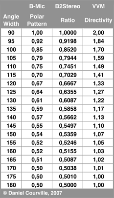
| | Monitoring & Mixing in Stereo When recording in B-Format, the opportunities of live monitoring in surround sound will be, for numerous reasons ranging from the practical to the financial, not too frequent. The need rises then for adequate monitoring in stereo over headphones or loudspeakers. There’s also the need for straight stereo mixes, not UHJ encoded, of B-Format recorded and encoded material. From its inception, the control unit of a Soundfield microphone always offered a stereo output for monitoring and mixing. This ability is also offered in Soundfield’s SurroundZone plug-in. York’s B-Mic and our B2Stereo are available for that exact purpose and McGriffy’s Visual Virtual Microphone (VVM) will also allow B-Format to stereo decoding. The choice of the virtual microphones stereo angle and polar pattern, while always being a question of producers’ preferences, must take into account the need for adequate monitoring in a recording session. So certain microphone pairs have to be avoided for monitoring a B-Format recording session. Two obvious pairs come to mind: a 90° pair of figure-8s and a 180° pair of cardioids. The former pair because the W channel will be absent in the monitoring output and the latter because the X channel will be absent. Good all around stereo pairs for monitoring are 25/75 hypercardioids at 110° to 33/67 hypercardioids at 120°. Such pairs give roughly equal weighting to all B-Format channels, have frontal dominance, but also have reach in the back quadrant and will put the maximum sensitivity of one mic into the null point of the other, thus providing maximum channel separation. In post-production, the choice of a stereo pair totally becomes a question of taste, but the «maximum against null» characteristic of the 25/75 hypercardioids at 110 °, that yields maximum separation, can be extended to all stereo angles between 90 and 180°. At 90°, a pair of fig-8s will put the maximum point of one fig-8 into the other fig-8 null point. At 180°, a pair of cardioids will put the maximum point of one mic into the other's null point. So there’s a continuum of those combinations, the 41/59 supercardioids at 135° being the mid-course combo. While reminding of the MS stereo technique, this continuum of «maximum against null» pairing is in a way doing the opposite of MS. In MS, the wider the stereo angle, the closer the virtual microphones are to the fig-8: the extreme case being a MS stereo angle of 180° with a pair of opposite fig-8s along that axis. This pair is totally unusable. With the «maximum against null» continuum, the angle/polar pattern relationship is inverted: the wider the angle, the closer the pattern is to cardioid. Here’s a chart of the «maximum against null» pairing with the B-Mic, B2Stereo and VVM. | | |  Non time-aligned Native B-Format channels Non time-aligned Native B-Format channels
| | Interchannel Time Alignment Without going into the debate over coincident techniques versus non-coincident techniques for stereo and surround recording, coincident microphone techniques will theoretically yield precise sound objects localization in playback. But the theory can be negated by the reality of the physical dimensions of the microphones involved in a coincident technique. Since it’s impossible to put all the mic capsules in the same point in space, localization in coincident techniques, native B-Format included, will be affected by the sound objects vertical angular offset relative to the horizontal plane of the stereo or surround microphone setup. The horizontal planeHorizontal plane of Native B-Format assembly is the result of the microphones sound capture axes: the axes are perpendicular to the microphones diaphragms. For example, if we have a sound object with a vertical offset of about -45° relative to the native B-Format assemblyA sound object with a vertical offset of about -45° relative to the native B-Format assembly, the offset will lead to differences in the moment of sound arrival at the three diaphragmsDifferences in the moment of sound arrival at the three diaphragms as viewed in a DAW. Once monitored in stereo or surround, these differences will blurry the sound object localization: even if the levels are right in the B-Format channels, a few samples of difference will affect spatial rendering. The sound object is less focused (or larger than its actual physical dimensions) and less precise in position. There’s a few strategies to correct the time difference. At the recording venue, it’s possible to lower the difference by physically tilting the assemblyPhysically tilting the Native B-Format assembly towards the general sound source. While not eliminating the time difference, it will reduce it: if no other time correction is applied in post-production, this tilting should always be done to minimize as much as possible the difference. In the case of acoustic music recordings, the assembly tilting can also help balance the sound between the first rows of musicians and the last rows. An ensemble physical depth in a concert hall, while usually resulting in an acceptable sound on site, will sometimes lead to excessive depth in stereo or horizontal surround playback (probably a result of established esthetics in acoustic music recording and incomplete spatial cues in playback). So by aiming the B-Format assembly main axis at the last row, the first rows, that are closer to the assembly, will be picked up in a less sensitive region: this will reduce amplitude differences between front and back and could eliminate the need for spot microphones. The tilting can of course also be done to a B-Format signal out of a Soundfield-type mic, except that it will be done by signal processing in post-production. Ultimately, the time correction strategy that will work the best is post-production sample-based alignmentSample-based time alignment in a DAW in the DAW. To be the most effective, this technique needs specific audio information recorded at the venue: to take a historical cue from cinema, a slate can be used to produce a time alignment signal. The short impulsive sound will produce an easily identifiable spike in the DAW. If a slate is not available, a few single hand claps can also work. We recommend slating at the corners of the performing ensemble and in front of all the spot microphones: all microphones should have their own tracks. Once recorded, the slate will permit easy alignment using sound file sliding in the trackThe slate will permit easy alignment using sound file sliding in the DAW or by using a sample-based delay plug-in: we prefer the latter since it allows easier tweaking. We currently use Metric Halo ChannelStripMetric Halo ChannelStrip in this fashion. Sample-based time alignment will benefit greatly from high sample rates (96 kHz and up): it will allow for greater accuracy in the process, even if the final product is at low sample rate (44.1 and 48 kHz). Of course, the alignment must be done before downsampling. A final word on time alignment: by nature, it will always be a compromise. Optimizing the time alignment for a particular vertical offset will degrade another. It’s up to the engineer and producer to choose what sound objects they want to have a more precise localization and what other sound objects won’t suffer, or even might benefit, from having a more blurry localization. |

© Daniel Courville, 2007-2021 | | | |
| |


